Power Quality Measurements:

The N-Conductor & Harmonics

In power quality measurements, odd harmonics such as the 15th, 21st & 27th are often violated. What are harmonics anyway, how does this circumstance occur and what influence does this have on the neutral conductor. This article deals with these questions and sheds light on this matter.

Definition of Harmonics

Due to the increasing number of non-linear consumers, more and more network feedbacks occur which can be characterised by a non-sinusoidal current. The TÜV SÜD defines harmonics as follows:

Harmonics are integer multiples of the mains frequency. They are caused by non-linear loads such as discharge lamps (e.g. energy-saving lamps), overloaded transformers, power supply units with peak-value rectifiers and by the use of power converter valves, e.g. rectifiers, frequency converters, regulators, UPS systems. The characteristic of these consumers and equipment is a non-sinusoidal current or a current flow that is periodically switched on and off. Generators whose winding technology allows the generation of harmonic voltages (harmonic fields) also cause harmonic currents when connected to the mains. These non-sinusoidal quantities can be traced back to sinusoidal quantities using suitable mathematical procedures (Fourier analysis). In addition to the fundamental frequency (in Europe: 50 Hz), they also contain integer multiples, the so-called harmonics. These harmonic currents cause voltage drops at the mains impedances or at the generator impedance. These voltage drops (harmonic voltages) are superimposed on the fundamental frequency (50 Hz) and distort the sinusoidal shape of the mains voltage. As a result, the trouble-free operation of other consumers (e.g. motors, generators, capacitors) can be impaired.

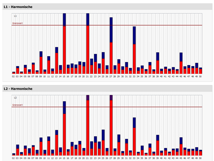
These harmonics can be detected by power quality measurements. Figure 1 shows a typical power quality measurement the case as described above has occurred. At first glance, the harmonics are exclusively odd and divisible by three.

Figure 1: Limit value violation Report according to EN 50160

Effects of single-phased devices

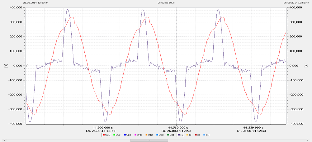
Nowadays, more and more single-phase devices are used that are controlled via a switched-mode power supply. In the home area, these are, for example, computers, game consoles and many other household appliances. Nowadays, these devices no longer have a transformer connected upstream, but a switched-mode power supply. In most cases, a bridge rectifier is built into the input of these switching power supplies, which absorbs the current in the form of pulses. In the past, the current was taken up sinusoidal by a resistive load. Figure 2 shows a measurement of the pulse.

Figure 2: Input circuit with B2

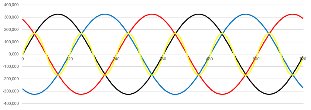
Decomposing the current into its spectrum, all odd harmonics are present. The harmonics divisible by three add up on the N conductor. This is because the phases L2 and L3 are 120° out of phase in the three-phase system. The 120° phase shift is of course also the time shift in which a full sinusoidal oscillation of 150 Hz is carried out as shown in figure 3. It can be seen in the figure that after 120° a full sine wave has been passed through and the next phase L2 then begins. If we now assume that similar loads are installed in the network on all three phases, then the third harmonic of the phase position for phase L2 and L3 would certainly also be in a similar position.

If the load on the three phases L1, L2 and L3 are symmetrical and loaded with 100 A, then the N conductor is not loaded. However, this is only true for the fundamental and for all harmonics that are not divisible by 3. If you can measure 10 A on all phases for a fifth harmonic, then you could also see only 0 A on the N conductor. The third harmonic has a special feature: since the initial position is exactly 120°, all samples of the phases L1, L2, L3 and N conductor must add up to 0. If the phases overlap exactly, this means that three times the current must flow on the N conductor. This circumstance also applies to the double and triple frequency, as well as the sixth or ninth harmonic. However, it is the case that mainly odd-numbered harmonics are found during investigations in the network and even-numbered harmonics hardly occur as a rule.

Figure 3: Sine oscillations three-phase + 150

Effects of current harmonics on the electrical grid

In conclusion, it can be stated that current harmonics with an ordinal number divisible by three overlap to a triple magnitude with symmetrical loading in the neutral conductor. This poses a problem for the network in that the impedance of the network for the harmonics divisible by 3 is four times as large as for the fifth harmonic or the fundamental. With symmetry, no current flows from the fifth harmonic on the N conductor, but three times the currents can be measured from the third harmonic, which flow back to the transformer. Therefore, for the harmonics divisible by 3, it is always quite decisive at which point in the network these harmonics are evaluated in the network. In the case that measurements are made relatively close to the transformer, a harmonic divisible by three is usually very inconspicuous here. However, the further one moves away from the transformer towards the consumer, the harmonics divisible by three increase rapidly on the voltage: much faster than a fifth or seventh harmonic would do.

The trend towards grids with higher-loaded harmonics cannot be prevented due to the large number of single-phase devices. All these devices increase the level of the harmonics divisible by three, such as the 3rd, 15th or 21st harmonic. In the meantime, the standards have reacted and increased the compatibility levels that are permitted for the public grid. For example, the compatibility level in the current EN 50160 for the 15th harmonic has been increased from 0.5 % to 1.0 %. If power quality assessments are carried out nowadays, the stored limit values in the measuring devices should be correctly set to the currently valid limit values

Author
Jürgen Blum, Product Manager Power Quality Mobile

Want more information about our products?

Contact us here!


Contact

News from the product group

PQMobil - News

General Knowledge

Voltage Monitoring

Find out everything you need to know about voltage monitoring in this article. What is voltage monitoring, why is voltage monitoring essential for both energy supply companies and industrial companies and how is it implemented in compliance with standards?

Read more

General Knowledge

What Is Load Profile Measurement/Power Measurement?

This article explains the definition and difference between load profile measurement (RLM), power measurement and measuring the standard load profile. These are important methods for accurately recording energy consumption in commercial, large industrial plant as well as in the public energy grid.

Read more

Training Video

»PQMobil« Training Video 4: Create and Configure PQ Reports With Software WinPQ mobil

This video explains everything about creating and configuring power quality reports with »WinPQ mobil«.

Read more

Training Video

»PQMobil« Training Video 3: Usability & Functions of the PQ-Box App

This video gives you an introduction to the usability and functions of the »PQ-Box App« for our portable power quality analysers.

Read more

Training Video

»PQMobil« Training Video 2: Menu Navigation and Operation of the PQ-Box

In this short introductory video, we present to you how to navigate and operate our portable power quality analysers »PQ-Box 150«, »PQ-Box 200« & »PQ-Box 300« of the PQ-Box family.

Read more

Training Video

»PQMobil« Training Video 1: Getting Started with the PQ-Box

This video shows in detail how to connect the »PQ-Box« and record measurements. The »WinPQ mobil« software is then used to visualize and analyse the measurement data and create a report.

Read more

General Knowledge

Residual current

In this article, you will learn about residual current measurement & residual current monitoring and why it is important to measure residual current.

Read more

General Knowledge

Power Quality

Good power quality is characterized by the fact that the mains voltage actually arriving at the consumer matches the mains voltage promised by the utility company.

Read more

General Knowledge

Reactive power – definition, calculation and measurement

The key role of reactive power in electrical engineering: definition, calculation, measurement and the differences to active power and apparent power. Find out how reactive power influences the efficiency of electricity grids and shapes energy transmission.

Read more

General Knowledge

What is apparent power and how is it calculated?

This article addresses the question of what apparent power is and how to calculate it. An understanding of apparent power is crucial for the correct dimensioning of inverters and therefore for the optimum efficiency and performance of photovoltaic systems.

Read more

Info letter

Information Letter No. 24: Integration guide for the metering of a power plant according to the Requirements for Generators (2016/631) RfG

Integration guide for the measurement of a power plant (EZA) according to VDE-AR 4110 and VDE-AR 4120.

Read more

Info letter

Info Letter No. 23: Direction of harmonics Sources of harmonics in the power system

Le sens du flux de puissance des harmoniques est déterminé par le signe de la puissance activ

Read more

Info letter

Info Letter No. 22: Definition of power measurements according to the standards DIN 40110-2 and IEEE 1459

There is a wide range of electronic measuring devices for the digital measurement of power...

Read more

Info letter

Info Letter No. 20: Capacitance of conductors

In the conductors of electrical power supplies, a distinction is made between the operating capacitance...

Read more

Info letter

Info Letter No. 19: The evaluation of power quality and detection of interference in medium voltage network

For various reasons, interest in the continuous monitoring of network quality in medium-voltage...

Read more

Info letter

Info Letter No. 8: Apparent power and reactive power in three-phase networks

The range of electromechanical and electronic measuring devices in analog - and digital technology...

Read more

Info letter

Info Letter No. 5: Zero sequence voltage in three-phase networks

With balanced network operation and inequality of the impedances in the consumer circuit, the phase...

Read more

Info letter

Info Letter No. 4: Summation of Alternating Currents

For the parallel connection of power sources, the principle of superposition applies, when all resources...

Read more

Info letter

Info Letter No. 2: Measurement Transformers in three-phase networks (Part 2)

In a symmetrically loaded three-wire three-phase network, a two-pole insulated voltage transformer...

Read more

Info letter

Info Letter No. 1: Measurement Transformers in three-phase networks (Part 1)

The direct connection of measuring devices into the network is limited for safety reasons to values...

Read more

Special Publication

Ferrari´s Meter vs. Electronic Meter

This technical report analyzes a power measurement at a large industrial customer. The customer records very high currents and fifth harmonic voltages during production time, which leads to poor voltage quality.

Read more

Special Publication

Angle determination of voltage and current harmonics in practice

Today's devices and equipment such as switched-mode power supplies, frequency converters, regulated drives, charging devices for e-mobiles or LED lighting work internally with high clock frequencies in order to regulate power efficiently. These can lead to both conducted and field-bound (coupled) influences in the energy grid. In this technical report, we explain how you can detect these sources of interference in the grid using suitable measuring technology.

Read more

General Knowledge

All „Supra“ with your grid?

Today's devices and equipment such as switched-mode power supplies, frequency converters, controlled drives, charging devices for e-mobiles or LED lighting work internally with high clock frequencies in order to regulate power efficiently. These can lead to line-borne as well as field-borne (coupled) interference in the power grid. In this technical report, we explain how you can detect these sources of interference in the grid using suitable measurement technology.

Read more

General Knowledge

Power Quality Analysis: Tips and Tricks II

Useful tips & tricks for handling Power Quality measuring devices and typical user errors - now in our two-part article! This article provides further insights and practical tips and application examples for power quality analysis.

Read more

General Knowledge

Power Quality Analysis: Tips and Tricks I

Useful tips & tricks for handling Power Quality measuring devices and typical user errors - now in our two-part article! This article explains tips and tricks for performing power quality measurements. It explains which connection errors can be made and which preliminary considerations should be made before using a measuring device.

Read more

Contact request:


* Mandatory

Your data is being processed

a-eberle kontakt newsletter ×

Our seminars &
webinars

► Register here!

x