In this technical article, Gerald Jacob (Product Manager »EORSys«) uses a specific example from the large German distribution system operator (DSO) »Netze BW GmbH« to show how energy utilities can meet the challenges of the energy transition in the medium and low-voltage grid with future-proof secondary substations. A standardised partial digitisation of secondary substations guarantees a reliable energy supply in the future thanks to improved grid transparency, and increases cost efficiency in the operation and maintenance of secondary substations. Start the video to find out more.
Challenges of the Energy Transition
EOR-3DS as a digitisation unit for secondary substations
The increasing demand for renewable energies and the growing number of electric vehicles pose major challenges for the electricity distribution grid. In Germany, for example, according to the Renewable Energy Sources Act (EEG) 2023 and the current coalition agreement, the share of renewable energy is to be increased to at least 80 per cent by 2030. However, the current figure stands at just 56 per cent.
As in many other countries around the world, a massive increase in installed wind power capacity and a multiplication of installed photovoltaic capacity will be required in the future. In addition, the expansion of heat pumps is also being strongly promoted in many countries. The reason for this is the worldwide transition from fossil fuels to renewable energy sources. In Germany, for example, heating systems in new buildings will have to be powered by at least 65 per cent renewable energy from 1 January 2024. Another important point is e-mobility: the worldwide number of electric vehicles is to be increased by a factor of 12 by 2030.

Challenges for distribution system operators based on the example of German DSO »Netze BW GmbH«
The specific challenges for distribution grid operators are highlighted using the example of the large German distribution grid operator Netze BW. The medium and low-voltage grid is often not sufficiently monitored, which can lead to bottlenecks. Secondary substations are mostly not remotely switchable, which makes it difficult or impossible to react quickly to grid problems.
Digital secondary substations (DSS) are becoming a key element for distribution system operators (DSO) in terms of automation, monitoring, and efficient operations of their networks. The DSS will be a vital element of the future actively operated smart grid and thus DSOs as well as manufacturers will have to face new challenges such as large-scale roll-outs of networked devices distributed over the whole power grid.
Compared to classical offline devices, connected devices demand more attention in terms of the associated management and operation processes. For example, a continuous patch management over thousands of devices needs to be realized for maintaining proper IT security standards and for providing functional updates. Manual processes cannot cope with the related huge amounts of tasks in an acceptable amount of time and in an economic way.
Netze BW has therefore defined a new management and operations architecture together with a standardized device for ring main units (RMU), the process interface and detection unit (PIDU).
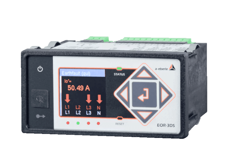
When used as a PIDU in the digital secondary substation, our new EOR-3DS fault indicator combines classic earth fault and short-circuit location with the necessary digital interface functions. This turns the short-circuit and earth-fault indicator into a completely new class of device: the EOR-3DS as digitisation unit for secondary substations.
Find out more about the EOR-3DS in the application at Netze BW here:

Application Report: EOR-3DS as Digitisation Unit for Secondary Substations
Cost efficient management of digital secondary substations: fault indicator EOR-3DS as digitisation unit for secondary substations
Quick Q&A With Gerald Jacob
(Product Manager »EORSys«)
At the official opening of the standardised digital secondary substation at Netze BW
Digital secondary substations with earth fault and short-circuit indicators can revolutionise grid monitoring and controlling. They offer a way to operate the power grid more efficiently and reliably.
Digitalisation of the Distribution Grid
Scope and Requirements
A comprehensive, standardised approach is required for the digitisation of the distribution grid. This includes scaling the conversion to digital secondary substations and implementing a centralised management and operating system.
Steps Towards the Digitisation of the Distribution Grid:
- Standardised processes and solutions for mass rollout
- Centralised management and operating system for remote maintenance and updates
- Scaling the conversion to digital secondary substations depending on grid dimensions and requirements
Benefits of Digital Secondary Substations
- Improved grid transparency and visibility
- Basis for grid automation and autonomy functions
- Cost-efficient operation due to remote controllability and remote parameterisation

Cost Efficiency of Digitisation
The roll-out of digital secondary substations (DSS) involves initial costs, but these can be spread over many units as the number of DSS increases, leading to a significant reduction in costs.
- Initially higher costs per station
- Cost reduction through scaling and mass rollout
- Long-term savings through more efficient operation and maintenance
Conclusion and Outlook
The digitisation of the distribution grid through DSS offers a promising solution to meet the challenges of the energy transition. Through structured implementation and the use of modern technologies, distribution grid operators can operate their grid more efficiently and reliably. The future holds many more opportunities for DSS:
- Continuous technical development of DSS
- Integration of new technologies such as AI and other IIoT applications for even smarter grids
- Cooperation between industry, research and politics for a sustainable energy future
Our Combined Earth Fault & Short-Circuit Indicators EOR-1DS & EOR-3DS in Comparison
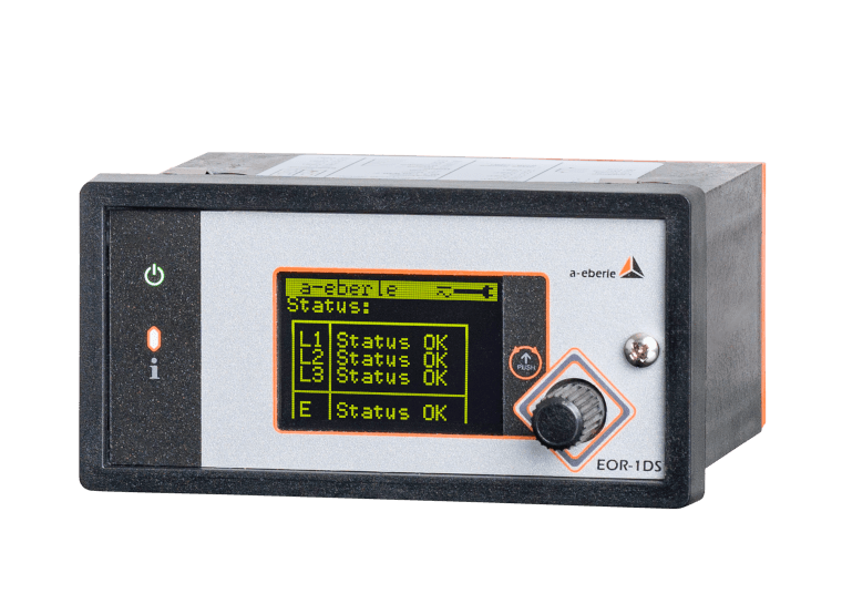
EOR-1DS: The Solution for Analog Secondary Substations
EOR-1DS offers a cost-effective solution for analog secondary substations by transmitting data to the control centre and enabling remote monitoring. It enables non-directional earth fault and short-circuit indication, and can optionally also provide directional indication methods.
Functions of EOR-1DS:
- Transfer data to control centre
- Remote monitoring of analog secondary substations
- Non-directional earth fault and short-circuit indication
- Option for directional indication with additional sensors
- Voltage measurement and power measurement integrated
EOR-3DS: The Solution for Digital Secondary Substations
The EOR-3DS offers advanced features for DSS, including a wider range of earth fault and short-circuit algorithms and a variety of SCADA protocols for communication.
Functions of EOR-3DS:
- Extended range of earth fault and short-circuit algorithms
- Compatibility with a wide range of low power sensors
- Remote monitoring of fault records and logbooks
- Fully programmable
- Support for various SCADA protocols including MQTT IIoT and MQTT Management & Operations
Quick Comparison: EOR-1DS vs. EOR-3DS
Find the right short-circuit and earth fault indicator for your application.
EOR-1DS
The fault indicator for
analog secondary substations
EOR-3DS
The fault indicator for
digital secondary substations
qu2 transient algorithm
Transient earth fault methodDirectional short-circuit and earth fault detection
Pulse location
❌
In preparation for EOR-1DS❌
In preparation for EOR-1DS❌
❌
Simple operation and parameterisation without software
❌
Extensive cyber security features✔️
Flash memory up to 32 GBCapacitive in parallel with VDS systems, low power sensors (two-wire technology) and classic transducers
Rogowski folding transducers, low power sensors (two-wire technology) and classic transducers
Modbus RTU
❌
❌
❌
❌
qu2 transient algorithm
Transient earth fault methodDirectional short-circuit and earth fault detection
Pulse location
Wattmetric method cos(φ)
Reactive power direction sin(φ)
qui-Method
Restriking faultsHarmonics method
Open setup as required with »AEToolbox« software
Certificate handling, user/role concept and encrypted connections
Extensive cyber security features✔️
Flash memory up to 32 GBCapacitive in parallel with VDS systems, Low power sensors (two-wire technology or RJ45) and classic transducers
Low power sensors (two-wire technology or RJ45) and classic transducers
Modbus RTU/TCP (Incl. “Modbus Master”)
IEC 60870-5-101 / 104, IEC 60870-5-103 Including Fault Records, IEC 61850 GOOSE, DNP 3.0
MQTT Management&Operations
MQTT IoT
MQTT protocol for centralised firmware rollouts
as well as remote mass parameterisation & data transfer to control centre in IIoT environment


