Definition of Harmonics
Harmonics are waves whose frequencies are an integer multiple higher or lower than those of the fundamental oscillations. They arise due to non-linear loads in the grid when the electrical voltage is distorted due to various influencing factors.
Causes of Disturbances/Harmonics in the Power Grid
The Change in Energy Technology

In order to utilise energy more efficiently, we now control many things using power electronics. For example, an asynchronous motor is often replaced by a frequency converter-controlled drive or an appliance is fitted with a switching power supply instead of a transformer.
In contrast to the old technology, the new appliance technology generally no longer draws sinusoidal current from the grid. Power quality measuring devices break down this current into the spectrum of all frequencies. In power quality measurement, we now subdivide system perturbations into harmonics, interharmonics and, more recently, supraharmonics.
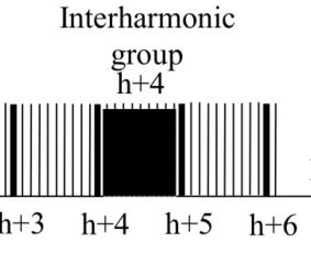
We define harmonics as multiples of the fundamental (example 250Hz = 5th harmonic for a 50Hz fundamental). If frequencies lie between two integer multiples of the fundamental, we refer to them as intermediate or interharmonics. In power quality measurement technology and in given the standards, all interharmonics of a range are generally summarised as one value (example: all frequencies between >350Hz and <400Hz are included in the 7th interharmonic).
Synonyms
In electrical engineering, terms are often used synonymously to describe harmonics:
- Harmonic
- Mains harmonic
- Harmonic currents
Significance of Harmonics in Connection With EMC
Harmonics are unwanted higher frequencies that are superimposed on the fundamental waveform and create a distorted wave pattern. These distortions can lead to electromagnetic interference (EMI) and thus impair electromagnetic compatibility (EMC). This is particularly important in the context of energy supply, as harmonics have a negative impact on the efficiency and service life of electrical devices and systems.
The EMC standard IEC61000-2-2 defines the rules of the game for the public grid today and, with its limit values up to 150 kHz, regulates whether a consumer introduces too high interference levels into the grid at the connection or whether a disturbed device has too low interference immunity. The right measurement technology can prove this. If the interference level is still below the limit values and a consumer is negatively affected, the interference immunity is probably too low. If the limit value of the standard is exceeded, it is almost certain that the source of the interference is causing excessive feedback into the grid.
Causes and effects
Harmonics in the AC grid are waves with frequencies that are higher than those of the fundamental oscillations of the grid frequency. They lead to a distortion of the sine wave of current and voltage and are an electromagnetic pollution of the power grid. These distortions are expressed as a percentage and are also referred to as total harmonic distortion (THD). The value refers to the ratio of all current or voltage harmonics to the fundamental frequency – usually the fundamental frequency of 50 hertz.
Typical causes and their clock frequencies/frequency ranges for grid perturbations that we have to reckon with in modern electricity supply grids today:
- Frequency inverter drive: 4kHz bis 20kHz
- Solar inverter (400V): 16kHz bis 22kHz
- Wind power plant (MV grid): 2kHz bis 6kHz
- E-Mobile charging station: 10kHz bis 80kHz
- Active mains filters: 8kHz bis 20kHz
- UPS systems 15kHz bis 25kHz
- ECG lights: 20kHz bis 200kHz
- Switching power supplies: 30kHz bis 300kHz
To summarise, it can be said that harmonics are a critical factor in the power supply that influences electromagnetic compatibility. They are caused by consumers and feeders, which cause negative feedback in the grid in the form of distortions in the electrical voltage. Harmonics occur above or below the fundamental frequency of the voltage sine wave and can also be described by various synonyms such as interharmonics or supraharmonics. Their effects on the efficiency and stability of power grids and electrical devices are considerable and should therefore not be underestimated.
Current video series – English subtitles available
Everything about power quality measurement and analysis for detecting harmonics and other grid interferences such as transients, flicker and voltage asymmetries.
Changes in Energy Technology – Part 1
This article, which was written in collaboration with the Schutztechnik.com portal, discusses the current changes in energy technology. It also looks at the effects of grid perturbations and the impact they have on the measuring devices we use today to detect faults in the grid.
Changes in Energy Technology – Part 1
Standards play a major role in power quality measurements. Accordingly, it is essential that these are also adapted to the new conditions in the course of the change in energy technology. In the second article in our series, we look at the current standards in the field of power quality and how they should be interpreted in relation to high switching frequencies.
Power Quality Measurements:
The N-Conductor & Harmonics
In power quality measurements, odd harmonics such as the 15th, 21st & 27th are often violated. But what are harmonics anyway, how do they come about and what influence do they have on the neutral conductor? This article deals with these questions and aims to shed some light on the subject.
Power Quality Measurements:
The Third Harmonic
The report ‘The neutral conductor & harmonics’ has already explained the special features of harmonics divisible by 3 and why they add up on the neutral conductor. This application report is intended to illustrate this once again using a typical measurement in the network and to show what needs to be taken into account for power quality measurements. The case described is about power quality problems in an office building.
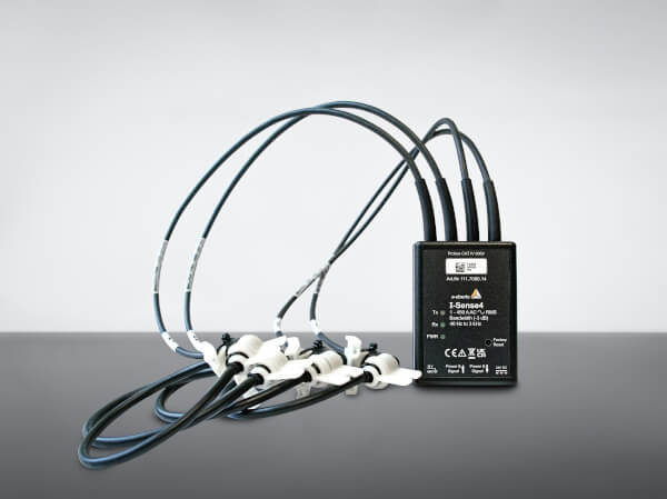
Four Ways to Measure Current
This video examines different methods of measuring current. It looks at how currents are measured using power analysers and current clamps. It looks at the respective advantages and disadvantages of different technologies such as shunts, normal current clamps, Hall effect sensors and Rogowski coils. The possible measurement errors are also addressed.
Angle Determination of Voltage and Current Harmonics
Who causes the harmonics, the customer or the energy supply company? And is it even possible to determine the direction of harmonics? Jürgen Blum, Product Manager ‘PQMobil’ and inventor of the A. Eberle PQ-Box, answers these questions in this video
Cos ϕ vs. Power Factor λ – Theory
This technical report discusses the distinction between the power factor and the cosine phi. The cosine phi, formerly often known as the ratio of active power to apparent power, has a different meaning for many consumers today. There is a striking difference in the definition of how the power factor or cosine phi is calculated.
Cos ϕ vs. Power Factor λ – Practice
This second technical report on the subject of reactive power and in particular distortion reactive power supplements the first article Cos ϕ vs. power factor theory. In this article, the voltage and current of an incandescent lamp are measured online using a network analyser (PQ-Box 200), which is regulated via phase angle control. This measurement example is used to illustrate the different types of reactive power.
Tips & Tricks 1 – How to Use Power Quality Measuring Devices and Typical Application Errors
This article provides you with valuable tips and tricks for carrying out power quality measurements. It explains which connection errors can be made and which preliminary considerations should be made before using a measuring device. With regard to the choice of measuring device, the decision between a mobile measuring device and a permanently installed power quality analyser is discussed.
Tips & Tricks 2 – How to Use Power Quality Measuring Devices and Typical Application Errors
This topic is divided into two posts (Tips and Tricks Part 1 and Part 2). This is part 2.
Types of Harmonics
When Is a Wave an Harmonic and When Is It Not?
Harmonics are waves that occur above or below the fundamental frequency. A harmonic oscillation is present if the movement of the oscillating body corresponds to the projection of a uniform circular motion and can be described by a sine or cosine function. Alternatively, an oscillation can be described as harmonic if the restoring force on the oscillating body is directed in the opposite direction and is proportional to the deflection of the body from its rest position. These conditions define when an oscillation is considered harmonic from a physical point of view.
Non-harmonic vibrations, on the other hand, do not fulfil these conditions. They do not exhibit uniform circular motion and the restoring force is not proportional to the deflection. In addition to harmonics, there are other types of network pollution that can be detected using suitable measurement technology.
Transients are short-term, sudden voltage or current peaks caused by rapid changes in the grid, such as lightning strikes, switching operations or sudden load changes. They can disrupt or damage electronic devices.
Flicker refers to rapid, repeated fluctuations in the mains voltage that cause lighting to flicker. These fluctuations are often caused by periodically fluctuating loads, such as welding.
Voltage asymmetries occur when the voltage in a three-phase network is unevenly distributed, which can lead to an uneven load on the phases and possible overheating. This can be caused by unevenly distributed loads, defective transformers or faulty cabling.
First, Second, Third and n-th Harmonics
The fundamental waveform is known as the 1st harmonic. The first harmonic has the same frequency as the fundamental. The second harmonic has a frequency that is twice as high as that of the fundamental, and the third harmonic has a frequency that is three times as high as the fundamental frequency. This continues for the nth harmonic, where the frequency is n times the fundamental frequency.
Interharmonics and Supraharmonics
Interharmonics occur when the frequencies of the oscillations are between integer multiples of the fundamental frequency. These can be caused by non-linear loads and lead to additional interference in the power grid.
Supraharmonics are harmonics whose frequencies are higher than the typical harmonic frequencies and can also lead to electromagnetic interference.
In summary, harmonic oscillations are characterised by their frequencies, which are integer multiples of the fundamental frequency. Non-harmonic oscillations do not fulfil this condition and can also lead to interference in the power grid. The first, second, third and nth harmonics have frequencies that are one, two, three or n times as high as the fundamental frequency. Interharmonic and supraharmonic harmonics include frequencies that lie between or above the harmonic frequencies and can also influence the power quality.
Origin and Effects of Harmonics
How and Where Do Harmonics Occur?
Harmonics occur in electrical networks due to non-linear equipment and devices that distort the sinusoidal shape of the current and voltage curves. Ideally, the electrical voltage should follow a perfect sinusoidal curve on which the polarity alternates evenly between positive and negative values. However, this uniform curve is only theoretical and is virtually impossible to find in reality today.
Causes of Harmonics
- Non-linear equipment: Devices such as transformers and fluorescent lamps have a non-linear characteristic curve that leads to harmonic oscillations.
- Power electronic equipment: Rectifiers, triacs and thyristors generate non-harmonic oscillations that disturb the mains.
- Switching power supplies: These are common in devices such as televisions, computers and halogen lighting and generate currents that lead to harmonic currents and therefore voltage distortions.
These factors disrupt the linear current consumption and lead to harmonics. Harmonics have been a recognised problem since the early days of electrical power distribution grids. However, with the further development and rapidly increasing use of frequency converters in modern appliances/consumers, these distortions are increasing significantly.
What Are the Negative Effects of Harmonics? What Risks Arise?
Harmonics can have a significant negative impact on electrical networks and the devices connected to them. Here are some of the most important problems and risks:
Additional Heating
Harmonics lead to additional heating of three-phase and alternating current motors and generators. This increased heating impairs the service life and efficiency of electronic devices.
Shortening the Service Life
Devices such as light bulbs can wear out more quickly due to the increased filament temperature. Harmonic vibrations can significantly shorten the service life of electrical devices.
Device Malfunctions and Overloads
Fluorescent lamps and the associated capacitors can be disturbed or overloaded by harmonics, which can lead to failures and malfunctions.
Destruction of Devices
High inrush peaks caused by harmonics can lead to a so-called neutral point shift, which can damage or destroy devices, especially in three-phase AC systems.
Malfunctions and Impairments
Harmonics can lead to malfunctions due to a shift in the zero crossings and the occurrence of multiple zero crossings. This affects power converters, synchronisation devices and parallel switching devices.
Impairment of Protective and Measuring Devices
Protective devices such as distance protection, overcurrent protection or differential protection can be impaired by harmonics. The accuracy of induction meters can also suffer.
Functional Impairment of Ripple Control Receivers
Harmonics can impair the functionality of ripple control receivers, which can lead to malfunctions and failures.
Malfunction of IT Systems
Harmonics can cause massive disruptions in IT systems, including operational failures, system crashes, module failures, interface defects, performance losses, data problems and screen flickering.
To summarise, harmonics pose a significant risk to the stability and efficiency of electrical networks and devices. They can lead to additional heating, shortened service life, device malfunctions and significant functional impairments. It is therefore important to take measures to reduce and control harmonics in order to ensure power quality and operational safety.
Measuring Harmonics With Class a Measuring Devices (IEC61000-4-30 Ed.3) by A. Eberle
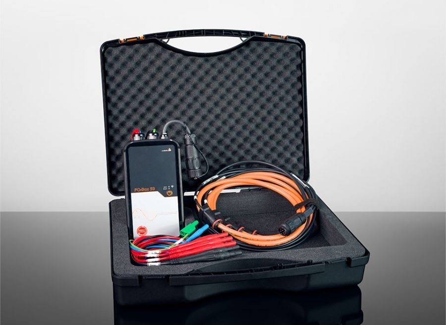
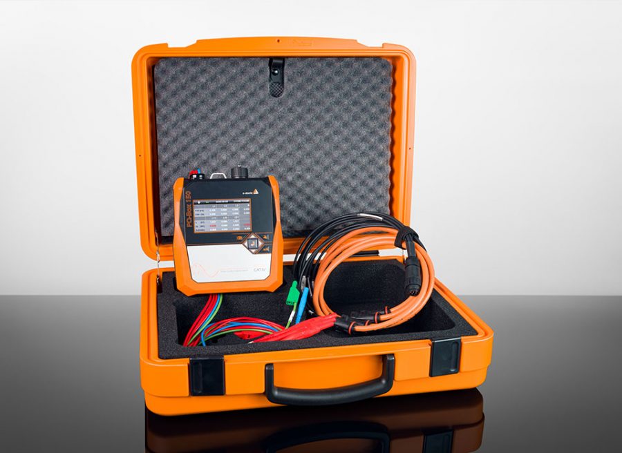
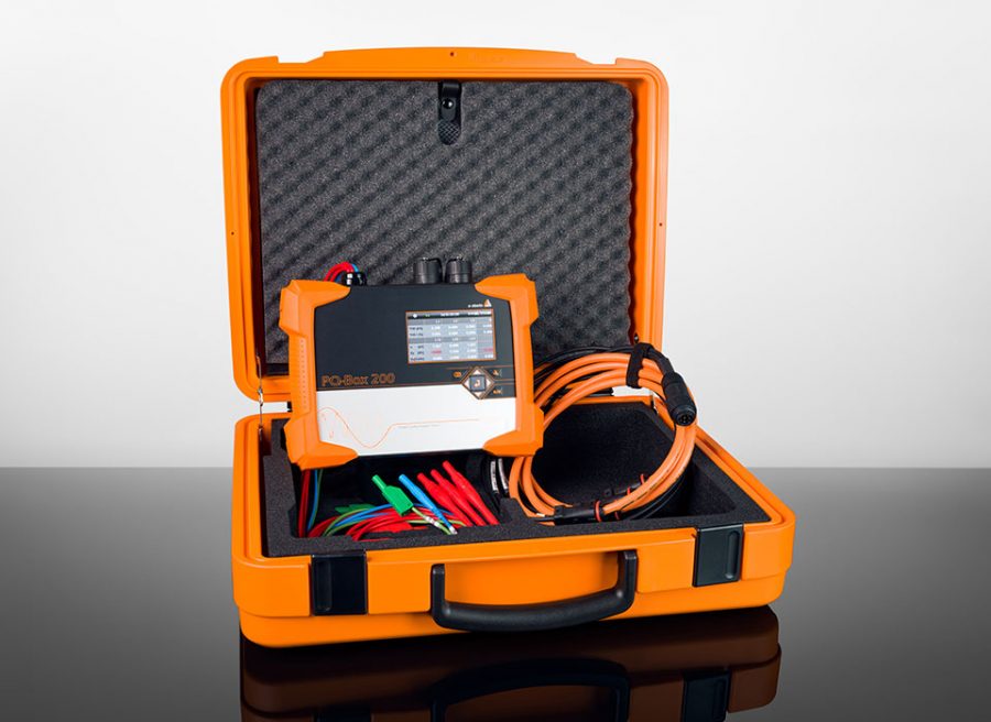
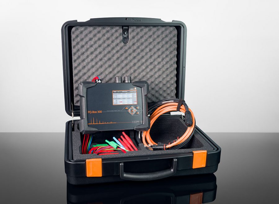
PQMobil – Our Portable Power Analysers
Reliably detect harmonics and mains pollution such as flicker, transients and voltage asymmetries.
The PQ-Box family consists of powerful, portable network and frequency analyzers, power measurement devices and transient recorders.
During their development, user-friendliness and practical considerations were the key concern. To quickly locate the cause of network errors, the devices are fitted with a wide range of trigger options.
All mobile network analyzers fulfil the high demands of IP65 and can also be installed and used outside. They also have a large operating temperature range of – 20°C to + 60°C.
And they fulfil every requirement of the measurement devices standards IEC61000-4-30 Ed.3, IEC62586-1 and IEC62586-2 Ed.2 for class A devices.
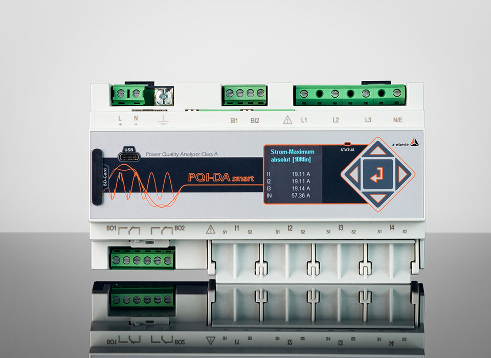
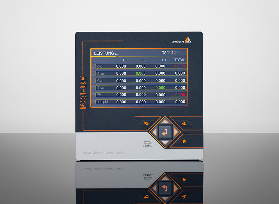
PQSys – Our Permanently Installed Power Quality Grid Analysers and Fault Recorders
Be prepared today and for the requirements of tomorrow.
The built-in fault recorders and network power quality analyzers PQI-DA smart, PQI-DE and PQI-D are the central components in systems handling all measurement tasks in low, medium and high-voltage networks. The analyzers can function as fault recorders with a scanning rate of up to 41 kHz, as power quality measurement devices to EN 50160 / IEC 61000-2-2/-4 or as power quality analyzers.
Above all, their components are suitable for monitoring special reference quality levels or characteristics agreed between an energy supplier and a customer, registering them and then presenting the results for analysis or storage.
Modern power quality devices work to the IEC 61000-4-30 standard, 3rd edition. This standard defines measurement processes to create a comparable basis for users.
Power Quality Services – Power Quality Analysis & Troubleshooting as a Service Directly From the Manufacturer
We Support You With Our Many Years of Experience With Your Power Quality Projects.
As a renowned manufacturer of portable high-end grid analysers and leading provider of permanently installed power quality measuring devices in Germany, we have technical know-how, many years of experience and advanced measuring technology.
We are at your side as a reliable and competent partner for all challenges in the field of power grid analysis. From the project definition to the final report. For more information on our power quality services, please click here to find out how we can best support you:

Power Quality Services
Expert Knowledge That Gets You Ahead
We offer you power quality audits with troubleshooting in accordance with EN 50160 and IEC 61000 and support you with our expert know-how. As an internationally recognised manufacturer in the field of premium portable power quality analysers, we can draw on a wide range of power network analysers with the appropriate accessories for your measurement projects.
Do you have any further questions about
measuring harmonics?
Our experts will be happy to help you!
Contact


