Cos ϕ vs. power factor λ

Definition of reactive power types

Cos ϕ vs. power factor λ

This technical report discusses the distinction between power factor and cosine phi.
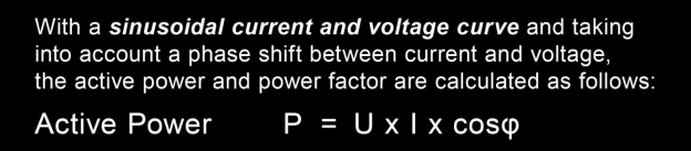
Cosine Phi, formerly widely known as the ratio of active power to apparent power, however, has a different meaning for many consumers today. There is a striking difference in the definition of how power factor or cosine phi is calculated.

The formula for the power factor (Lambda) shows that the latter represents the voltage multiplied by the fundamental current and the cosine of the angle Phi (phase shift between fundamental voltage and fundamental current).

1 Formula power factor lambda

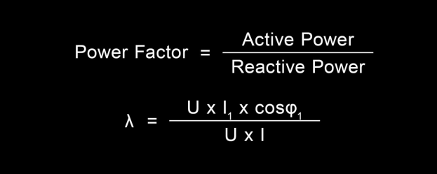
In relation to the apparent power (U x I), the power factor is defined as the ratio of active power to apparent power.

Only if both the current and the voltage in a network are sinusoidal (free of harmonics), the power factor and the cosine Phi are identical. However, this is rarely true nowadays, because in practice at least the current has harmonics and often deviates strongly from a pure sine wave.

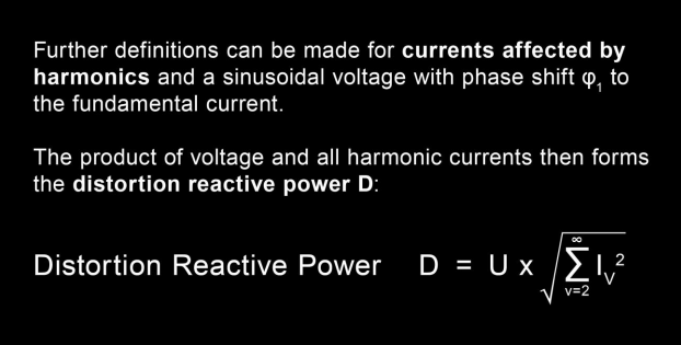
In this case, in addition to the fundamental reactive power, harmonic reactive power or distortion reactive power is also obtained in the network.

2 Power triangle as a three-dimensional construct

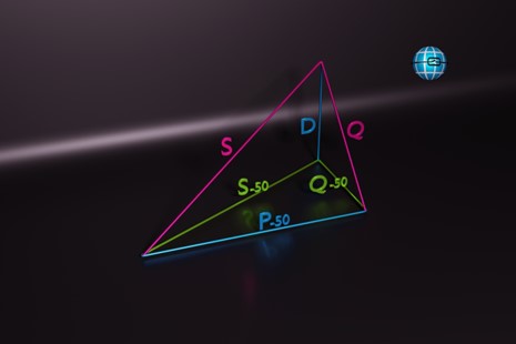
The power triangle, consisting of active power, reactive power and apparent power, has now expanded into a three-dimensional construct. This extension includes consideration of the fundamental reactive power (Q-50), which can be either capacitive or inductive. The angle between active and reactive power is thereby 90 degrees. The third dimension of the power triangle includes the distortion reactive power (D) of harmonics, which is at right angles to the fundamental reactive power. To obtain the total reactive power of a circuit, these must be summed squared. To attain the apparent power, the active power (Q) and the reactive power, which are at right angles to each other, must be summed squared.
The apparent power is defined by the formula voltage x current.

A practical example of this can also be found in the video shown here:

A PQ box is used to measure a voltage with a frequency of 50 Hertz. The current has a frequency of 150 Hertz. By multiplying the samples, a power is now calculated from these two frequencies. At certain moments, the power is positive and flows from the grid to the consumer. There is also a red power curve that is negative and in the negative range. By definition, this is where power is pushed from the consumer to the grid (negative sign of the power).

3 Voltage & current from the measurement example

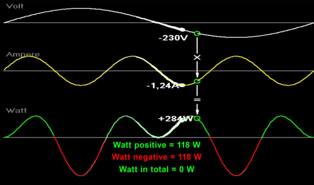
In power measurement technology, it is necessary to always integrate the power over the area. In the 50 hertz network, the smallest measurement interval is one sine half-wave, thus 10 milliseconds. To calculate the power, the area under the power curve is integrated over this period. In this example, integrating the green power curves above the zero line gives a value of 118 watts, while the larger red curve below the zero line has a value of minus 118 watts. The integral of the total power over 10 milliseconds gives a value of zero, indicating oscillating power, which is defined as reactive power. Although this reactive power loads our line and the transformer, it does not have to be generated as active power. In practice, all current harmonics are multiplied by the voltage fundamental oscillation to calculate the distortion reactive power. Since the basic voltage oscillation dominates and the other voltage harmonics usually do not play a major role, this can be neglected in the measurement technique.

Reactive power is a type of power that is present in an electrical network that is not used, but only serves to increase the network load and losses in the network.

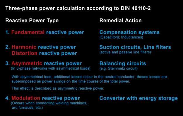
There are the following types of reactive power:

  • Fundamental reactive power
  • harmonic reactive power/distortion reactive power
  • unbalance reactive power
  • modulation reactive power

There are different remedies for each type of reactive power.

4 Reactive power types and their remedies

Reactive power refers to the deviation between the apparent power displayed in a network and the actual active power used by the equipment.

Unbalanced reactive power occurs when loads in a three-phase network are loaded unbalanced. This can occur, for example, due to different power on the three phases L1, L2 and L3. Although the apparent power and the active power per phase are equal in this case, a reactive power results in the overall system, which is called unbalanced reactive power. To reduce this reactive power, one can use, for example, an unbalance compensation system that compensates for the unbalanced currents and thus minimizes the reactive power

Modulation reactive power is caused by large fluctuations in the modulation of the current, such as in oscillation pack controllers. Today, there are many different types of reactive power, which modern power analyzers such as the PQ-Box evaluate and record individually.

5 – Selection menu power analyzer PQ-Box powers
6 – Reactive power types

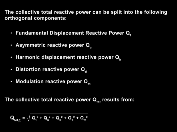
The collective total reactive power is the square sum of all reactive power types.


This collective total reactive power thus explains the deviation between active and apparent power. It should be noted that the collective reactive power never has a sign, since all reactive power types are summed squared and consequently the sign is always positive. Only the fundamental reactive power can have a sign. A minus sign if this is capacitive and a positive sign if this fundamental reactive power is inductive.

7 Example from industry: B6 bridge rectifier voltage and current L1

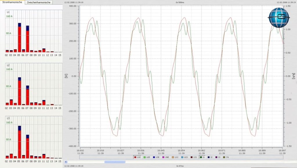
The use of a frequency converter serves as a practical example. In this case, a B6 bridge rectifier circuit with 4 diodes is installed before the drive. The three-phase voltages or currents are hereby rectified and sent to the input of the inverter. In Fig. No. 7, it is easy to see that the current and voltage are in phase, expressing a cosine phi of close to 1. However, power analyzers will indicate a large reactive power for this load, since the power factor (ratio of P to S) is 0.85. An analysis of the current shows that the fifth and seventh current harmonics are present in this case, up to 160A. These current harmonics result in a distortion reactive power.


Another video shows, on a practical example, the reactive power types on the basis of a phase angle control.

Autor
Jürgen Blum, Product Manager Power Quality Mobile

Want more information about our products?

Contact us here!


Contact

News from the product group

PQMobil - News

General Knowledge

Voltage Monitoring

Find out everything you need to know about voltage monitoring in this article. What is voltage monitoring, why is voltage monitoring essential for both energy supply companies and industrial companies and how is it implemented in compliance with standards?

Read more

General Knowledge

What Is Load Profile Measurement/Power Measurement?

This article explains the definition and difference between load profile measurement (RLM), power measurement and measuring the standard load profile. These are important methods for accurately recording energy consumption in commercial, large industrial plant as well as in the public energy grid.

Read more

Training Video

»PQMobil« Training Video 4: Create and Configure PQ Reports With Software WinPQ mobil

This video explains everything about creating and configuring power quality reports with »WinPQ mobil«.

Read more

Training Video

»PQMobil« Training Video 3: Usability & Functions of the PQ-Box App

This video gives you an introduction to the usability and functions of the »PQ-Box App« for our portable power quality analysers.

Read more

Training Video

»PQMobil« Training Video 2: Menu Navigation and Operation of the PQ-Box

In this short introductory video, we present to you how to navigate and operate our portable power quality analysers »PQ-Box 150«, »PQ-Box 200« & »PQ-Box 300« of the PQ-Box family.

Read more

Training Video

»PQMobil« Training Video 1: Getting Started with the PQ-Box

This video shows in detail how to connect the »PQ-Box« and record measurements. The »WinPQ mobil« software is then used to visualize and analyse the measurement data and create a report.

Read more

General Knowledge

Residual current

In this article, you will learn about residual current measurement & residual current monitoring and why it is important to measure residual current.

Read more

General Knowledge

Power Quality

Good power quality is characterized by the fact that the mains voltage actually arriving at the consumer matches the mains voltage promised by the utility company.

Read more

General Knowledge

Reactive power – definition, calculation and measurement

The key role of reactive power in electrical engineering: definition, calculation, measurement and the differences to active power and apparent power. Find out how reactive power influences the efficiency of electricity grids and shapes energy transmission.

Read more

General Knowledge

What is apparent power and how is it calculated?

This article addresses the question of what apparent power is and how to calculate it. An understanding of apparent power is crucial for the correct dimensioning of inverters and therefore for the optimum efficiency and performance of photovoltaic systems.

Read more

Info letter

Information Letter No. 24: Integration guide for the metering of a power plant according to the Requirements for Generators (2016/631) RfG

Integration guide for the measurement of a power plant (EZA) according to VDE-AR 4110 and VDE-AR 4120.

Read more

Info letter

Info Letter No. 23: Direction of harmonics Sources of harmonics in the power system

Le sens du flux de puissance des harmoniques est déterminé par le signe de la puissance activ

Read more

Info letter

Info Letter No. 22: Definition of power measurements according to the standards DIN 40110-2 and IEEE 1459

There is a wide range of electronic measuring devices for the digital measurement of power...

Read more

Info letter

Info Letter No. 20: Capacitance of conductors

In the conductors of electrical power supplies, a distinction is made between the operating capacitance...

Read more

Info letter

Info Letter No. 19: The evaluation of power quality and detection of interference in medium voltage network

For various reasons, interest in the continuous monitoring of network quality in medium-voltage...

Read more

Info letter

Info Letter No. 8: Apparent power and reactive power in three-phase networks

The range of electromechanical and electronic measuring devices in analog - and digital technology...

Read more

Info letter

Info Letter No. 5: Zero sequence voltage in three-phase networks

With balanced network operation and inequality of the impedances in the consumer circuit, the phase...

Read more

Info letter

Info Letter No. 4: Summation of Alternating Currents

For the parallel connection of power sources, the principle of superposition applies, when all resources...

Read more

Info letter

Info Letter No. 2: Measurement Transformers in three-phase networks (Part 2)

In a symmetrically loaded three-wire three-phase network, a two-pole insulated voltage transformer...

Read more

Info letter

Info Letter No. 1: Measurement Transformers in three-phase networks (Part 1)

The direct connection of measuring devices into the network is limited for safety reasons to values...

Read more

Special Publication

Ferrari´s Meter vs. Electronic Meter

This technical report analyzes a power measurement at a large industrial customer. The customer records very high currents and fifth harmonic voltages during production time, which leads to poor voltage quality.

Read more

Special Publication

Angle determination of voltage and current harmonics in practice

Today's devices and equipment such as switched-mode power supplies, frequency converters, regulated drives, charging devices for e-mobiles or LED lighting work internally with high clock frequencies in order to regulate power efficiently. These can lead to both conducted and field-bound (coupled) influences in the energy grid. In this technical report, we explain how you can detect these sources of interference in the grid using suitable measuring technology.

Read more

General Knowledge

All „Supra“ with your grid?

Today's devices and equipment such as switched-mode power supplies, frequency converters, controlled drives, charging devices for e-mobiles or LED lighting work internally with high clock frequencies in order to regulate power efficiently. These can lead to line-borne as well as field-borne (coupled) interference in the power grid. In this technical report, we explain how you can detect these sources of interference in the grid using suitable measurement technology.

Read more

General Knowledge

Power Quality Analysis: Tips and Tricks II

Useful tips & tricks for handling Power Quality measuring devices and typical user errors - now in our two-part article! This article provides further insights and practical tips and application examples for power quality analysis.

Read more

General Knowledge

Power Quality Analysis: Tips and Tricks I

Useful tips & tricks for handling Power Quality measuring devices and typical user errors - now in our two-part article! This article explains tips and tricks for performing power quality measurements. It explains which connection errors can be made and which preliminary considerations should be made before using a measuring device.

Read more

Contact request:


* Mandatory

Your data is being processed

a-eberle kontakt newsletter ×

Our seminars &
webinars

► Register here!

x