Summation of Alternating Currents

Info Letter No. 4

General Info

For the parallel connection of power sources, the principle of superposition applies, when all resources have a linear behaviour. This behaviour is the case with current transformers within the allowable load range and below a few thousand Hertz. It should be noted that in principle and device technically only simultaneous instantaneous values are added, not effective values!

Through the common load resistor RL of parallel current transformers a current flows that corresponds to the arithmetic sum of the instantaneous values of all the currents. It is assumed that the current transformers provide superimposed currents and the frequency limits (highest order of the harmonics) are not exceeded.

The arithmetic sum of the instantaneous values is not only dependent on the amount, but also the sign of the individual currents, so that for the summation the polarity of the current sources must be considered. With alternating currents of the same direction of energy flow, the polarity is related to the secondary terminals S1 (k) and S2 (l) of the current transformer.

Waveform of the total current

When summing equal frequency sinusoidal currents, the curve of iS has the form of a sinusoidal curve, with currents of unequal frequency the waveform of the total current i is no longer sinusoidal.

Waveform ot the total current for the summation of three currents
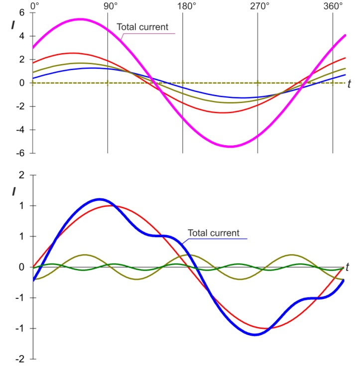
a) with the same frequency
b) with different frequencies

Sum of the instantaneous values

For the three-phase three-wire network with the same frequency sinusoidal currents, the simultaneous instantaneous values are ideally zero.

Effective value of the total current

For the calculation of the effective value of the total current from the momentary values of current with an arbitrary frequency/waveform the following applies:

I_{\sum} = \sqrt{\frac{1}{T}\int_{T}^{0}(i_{0} +i_{1}+i_{2}+...+i_{n})^{2} dt }
i_{0} +i_{1}+i_{2}+...+i_{n}

Arithmetic sum of the simultaneous current components

For the calculation only of the effective values of currents with different frequencies (e.g. equal value/ fundamental with harmonics) the following also applies:

I_{\sum} = \sqrt{I^{2}_{0} +I^{2}_{1}...+I^{2}_{n} }

I0 = Effective value of the direct current
I1 = Effective value of the fundamental
In = Effective value of the highest harmonic

Need more information?

Contact us!


Contact

Info-Letters

Click Through Our Info Letter Series

News from the product group

News

General Knowledge

Voltage Monitoring

Find out everything you need to know about voltage monitoring in this article. What is voltage monitoring, why is voltage monitoring essential for both energy supply companies and industrial companies and how is it implemented in compliance with standards?

Read more

General Knowledge

What Is Load Profile Measurement/Power Measurement?

This article explains the definition and difference between load profile measurement (RLM), power measurement and measuring the standard load profile. These are important methods for accurately recording energy consumption in commercial, large industrial plant as well as in the public energy grid.

Read more

Training Video

»PQMobil« Training Video 4: Create and Configure PQ Reports With Software WinPQ mobil

This video explains everything about creating and configuring power quality reports with »WinPQ mobil«.

Read more

Webinar

»PQSys« Webinar: PQ-Monitoring & Feeder Current Measurement in Low-Voltage Grids

Webinar recording from 17.04.2024: »PQSys - PQ-Monitoring & Feeder Current Measurement in Low-Voltage Grids«.

Read more

Special Publication

Experimental Validation of a Low-Voltage Regulator Model – Case Study of a Maltese Low-Voltage Grid

This application report addresses the integration of the »LVRSys® Low-Voltage Regulation System« into the low-voltage grid in Malta.

Read more

Training Video

»PQMobil« Training Video 3: Usability & Functions of the PQ-Box App

This video gives you an introduction to the usability and functions of the »PQ-Box App« for our portable power quality analysers.

Read more

Training Video

»PQMobil« Training Video 2: Menu Navigation and Operation of the PQ-Box

In this short introductory video, we present to you how to navigate and operate our portable power quality analysers »PQ-Box 150«, »PQ-Box 200« & »PQ-Box 300« of the PQ-Box family.

Read more

Training Video

»PQMobil« Training Video 1: Getting Started with the PQ-Box

This video shows in detail how to connect the »PQ-Box« and record measurements. The »WinPQ mobil« software is then used to visualize and analyse the measurement data and create a report.

Read more

General Knowledge

The Future of the Distribution Grid: Focus on Digital Secondary Substations

In this technical report, Gerald Jacob (Product Manager »EORSys«) uses a specific example to illustrate how distribution system operators can meet the challenges of energy transition in the medium and low-voltage grid with future-proof secondary substations.

Read more

General Knowledge

Earth fault explained – basics and functions of an electrical phenomenon

Everything you need to know about earth faults - from the basics, causes and examples to the consequences. Find out more in this article about earth fault clearing, compensation, location and the benefits of constant monitoring to ensure a safe power grid.

Read more

General Knowledge

Residual current

In this article, you will learn about residual current measurement & residual current monitoring and why it is important to measure residual current.

Read more

General Knowledge

Power Quality

Good power quality is characterized by the fact that the mains voltage actually arriving at the consumer matches the mains voltage promised by the utility company.

Read more

General Knowledge

Reactive power – definition, calculation and measurement

The key role of reactive power in electrical engineering: definition, calculation, measurement and the differences to active power and apparent power. Find out how reactive power influences the efficiency of electricity grids and shapes energy transmission.

Read more

General Knowledge

What is apparent power and how is it calculated?

This article addresses the question of what apparent power is and how to calculate it. An understanding of apparent power is crucial for the correct dimensioning of inverters and therefore for the optimum efficiency and performance of photovoltaic systems.

Read more

General Knowledge

Ready for the smart grid of the future?

All information about smart grids/intelligent power grids, the technology behind them, advantages, disadvantages, challenges and current distribution.

Read more

Info letter

Information Letter No. 24: Integration guide for the metering of a power plant according to the Requirements for Generators (2016/631) RfG

Integration guide for the measurement of a power plant (EZA) according to VDE-AR 4110 and VDE-AR 4120.

Read more

Info letter

Info Letter No. 23: Direction of harmonics Sources of harmonics in the power system

Le sens du flux de puissance des harmoniques est déterminé par le signe de la puissance activ

Read more

Info letter

Info Letter No. 22: Definition of power measurements according to the standards DIN 40110-2 and IEEE 1459

There is a wide range of electronic measuring devices for the digital measurement of power...

Read more

Info letter

Info Letter No. 21: The influence of the contact resistance at the earth-fault location on the zero sequence voltage UEN in compensated networks

The earth fault in compensated networks is usually presented without a contact resistance at the fault...

Read more

Info letter

Info Letter No. 20: Capacitance of conductors

In the conductors of electrical power supplies, a distinction is made between the operating capacitance...

Read more

Info letter

Info Letter No. 19: The evaluation of power quality and detection of interference in medium voltage network

For various reasons, interest in the continuous monitoring of network quality in medium-voltage...

Read more

Info letter

Info Letter No. 18: Transient relay for high resistance, intermittent and recurrent earth faults (Part 2)

Figure 3 can also be used for the determination of static earth faults. In an isolated network the entire...

Read more

Info letter

Info Letter No. 17: Transient relay for high resistance, intermittent and recurrent earth faults (Part 1)

The statistics show that earth faults constitute a large proportion of network faults. Conventional relays...

Read more

Info letter

Info Letter No. 16: Hot-spot temperature and service life of transformers

The failure of a transformer not only has major economic consequences for the energy supplier, it can...

Read more

Info letter

Info Letter No. 15: Earth fault location using the harmonic procedure (Part 2)

For the study of the behaviour of the harmonic currents and voltages in the compensated network, at...

Read more

Contact request:


* Mandatory

Your data is being processed

a-eberle kontakt newsletter ×

Our seminars &
webinars

► Register here!

x