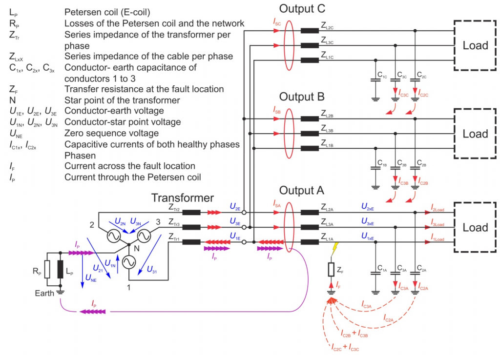
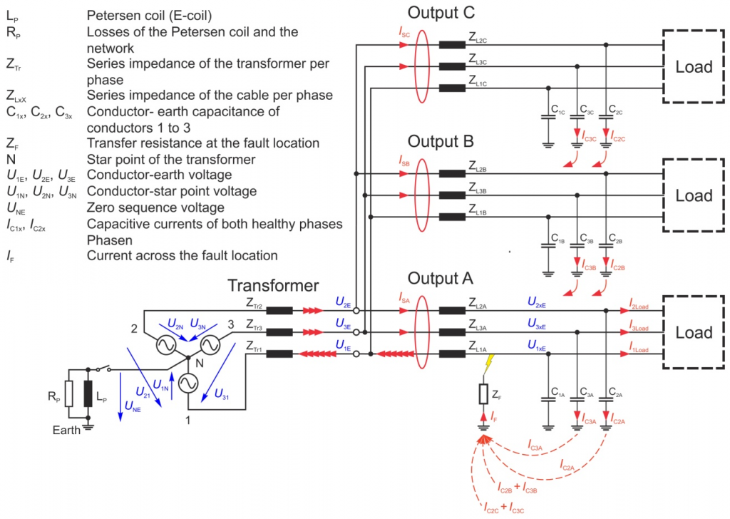
For the following considerations a network with three outputs and an earth fault in line 1 in output A is assumed. Due to the earth fault, line 1 is brought to earth potential and the phase-earth voltage of the two healthy lines is increased to Ö3 times. This increased voltage now drives a Ö3 increased current to earth through the conductor capacitance of the healthy conductor. The faulty conductor delivers no part of the current in the healthy outputs. The sum of all currents to earth flows through the point of failure and in the faulty output in the faulty conductor back to the transformer. If the total currents of the three conductors are measured at the beginning of the outputs and the zero sequence voltage UNE in the substation, the following statements can be made:
- The sum of the currents in the healthy outlets is capacitive and leads the zero sequence voltage UNE by 90°.
- The sum of the currents in the faulty outlets is inductive and the zero sequence voltage UNE leads by by 90°.
- The total current in the faulty output corresponds to the sum of total currents of the healthy outputs:
|ISA| = |ISB| + |ISC|
The direction of current can now be used for earth fault detection on the one hand in relation to the zero sequence voltage or on the other hand the search for the maximum current.
Earth fault location in compensated networks
If the network becomes larger, the total current flow through the point of failure achieves orders of magnitude at which on the one hand an existing arc can no longer be extinguished and where on the other hand the limits for the touch and step voltages are exceeded. A reduction of the current over the point of failure can be done by switching to a Petersen coil at the neutral point of the transformer.
From Figure 2, it is evident that the voltage U1N drives a current through the Petersen coil and the failure point to which the previously considered current over the failure point is contrary. By suitable adjustment of the size of the Petersen coil, the current through the fault site can be reduced to a small active component. Upon closer examination, with ideal compensation the currents from the phase-earth capacitance flow directly to the Petersen coil.
Although the ratios are improved at the point of failure by the Petersen coil, but that makes it difficult for the earth fault location, because with perfect compensation is now at the faulty output the same capacitive current is measured as if this output was healthy.
The simple differentiation between inductive and capacitive current, as used in isolated networks, is no longer possible. In the faulty output only a small active component has been added, for its determination however, very large demands are made on the accuracy of the transformer, especially in terms of angular error.
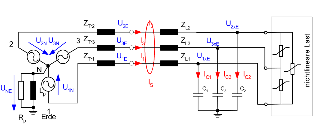
Occurrence of harmonic voltages
Due to non-linear loads in the network, harmonic currents are generated in the three conductors.
Since there is no connection in the load to earth, at any time the sum of the load currents is zero. On the other hand these harmonic currents produce voltage drops along the series impedance of the network and especially at the relatively high-impedance transformer impedance. These voltage drops lead to a distortion in the phase voltages U12, U23, and U31. Due to the symmetry of the phase-earth capacitances the distortion in the zero sequence voltage UNE cannot be measured. But this means that in a healthy network with symmetric capacitances no harmonic current flows across earth or across the Petersen coil, even if the network voltages include large harmonic voltages and the phase currents contain large harmonic currents.
It should be stressed once again that the distortion in the network voltage is essentially caused by the voltage drop at the transformer. Thus, the distorted line voltage is present throughout the network section, regardless of whether the non-linear loads are in output A or B or C.