The influence of the contact resistance at the earth-fault location on the zero sequence voltage UEN in compensated networks

Info Letter No. 21

Earth Fault in compensated networks

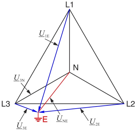
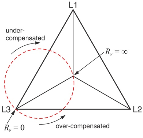
The earth fault in compensated networks is usually presented without a contact resistance at the fault location (RF= 0). In the vector diagram in the case of an earth fault the earth point then changes into a vertex of the voltage triangle.

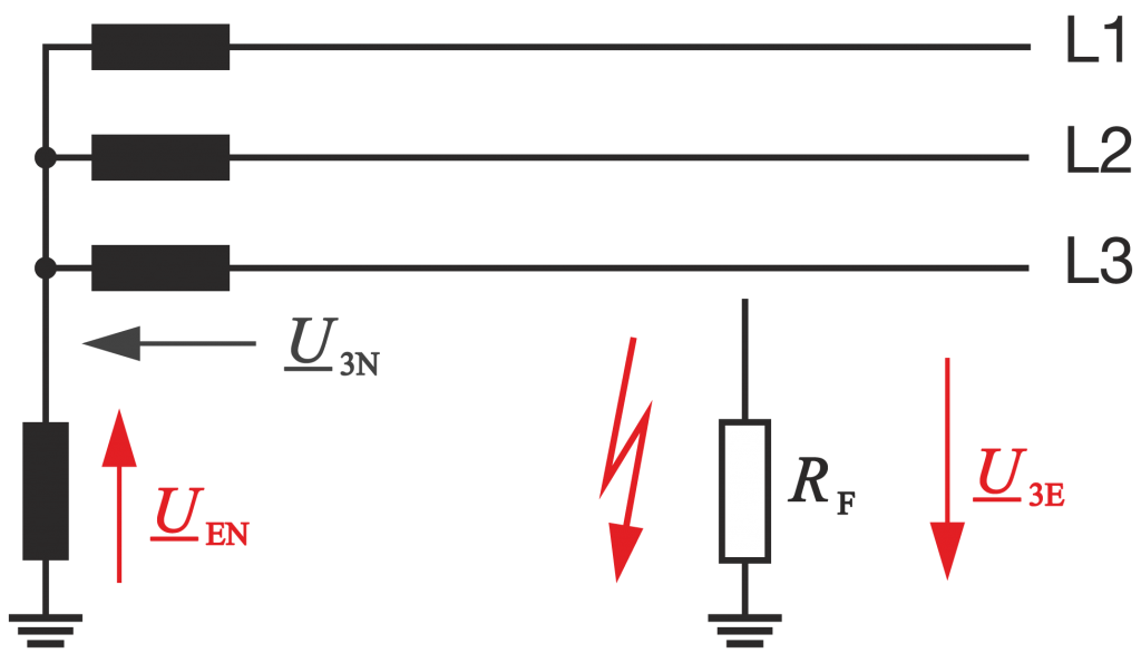
However, usually an arc occurs at the fault location with a finite resistance (RF¹0). As a function of the detuning v, the damping d and the resistance RF at the fault location, the earth point E at the fault location changes into a circular arc, in overcompensation counterclockwise and with undercompensation clockwise towards the centre of the voltage triangle. The location of the centre of the circle is determined by the detuning and damping.

The vector diagram of the voltages then changes and thus also the voltages at the phase-earth capacitances and the earth fault coils according to the magnitude and phase angle.

The new voltages can be calculated with the aid of the symmetrical components. The zero sequence is represented by a parallel resonant circuit consisting of the phase-earth capacitance, earth fault coil and discharge resistors.

You have a question?

Contact us!


Contanct now

Info-Letters

Click Through Our Info Letter Series

News from the product group

EORSys - News

General Knowledge

The Future of the Distribution Grid: Focus on Digital Secondary Substations

In this technical report, Gerald Jacob (Product Manager »EORSys«) uses a specific example to illustrate how distribution system operators can meet the challenges of energy transition in the medium and low-voltage grid with future-proof secondary substations.

Read more

General Knowledge

Earth fault explained – basics and functions of an electrical phenomenon

Everything you need to know about earth faults - from the basics, causes and examples to the consequences. Find out more in this article about earth fault clearing, compensation, location and the benefits of constant monitoring to ensure a safe power grid.

Read more

General Knowledge

Ready for the smart grid of the future?

All information about smart grids/intelligent power grids, the technology behind them, advantages, disadvantages, challenges and current distribution.

Read more

Info letter

Info Letter No. 20: Capacitance of conductors

In the conductors of electrical power supplies, a distinction is made between the operating capacitance...

Read more

Info letter

Info Letter No. 18: Transient relay for high resistance, intermittent and recurrent earth faults (Part 2)

Figure 3 can also be used for the determination of static earth faults. In an isolated network the entire...

Read more

Info letter

Info Letter No. 17: Transient relay for high resistance, intermittent and recurrent earth faults (Part 1)

The statistics show that earth faults constitute a large proportion of network faults. Conventional relays...

Read more

Info letter

Info Letter No. 15: Earth fault location using the harmonic procedure (Part 2)

For the study of the behaviour of the harmonic currents and voltages in the compensated network, at...

Read more

Info letter

Info Letter No. 14: Earth fault location using the harmonic procedure (Part 1)

For the following considerations a network with three outputs and an earth fault in line 1 in output...

Read more

Info letter

Info Letter No. 12: E-coil control: Resonance curve procedure – Location curve procedure

In "compensated networks" the current through the point of failure is minimised with the help of an...

Read more

Info letter

Info Letter No. 6: Detection of transient earth faults

When there is an earth fault in a conductor, at the start of the earth fault three events occur at the...

Read more

Info letter

Info Letter No. 4: Summation of Alternating Currents

For the parallel connection of power sources, the principle of superposition applies, when all resources...

Read more

Info letter

Info Letter No. 3: The E-coil in general

The earth fault compensation coil, e-coil or also called the Petersen coil after its inventor, is connected...

Read more

Webinar

»EORSys« Webinar: Short-Circuit & Earth Fault Detection in Digital & Analog Substations

Webinar recording from 07.05.2024: »EORSys - Short-Circuit & Earth Fault Detection in Digital & Analog Substations«.

Read more

Special Publication

Cost Efficient Management of Digital Secondary Substations: Earth Fault Indicator EOR-3DS as Digitisation Unit for Secondary Substations

Digital secondary substations are becoming a key element for distribution system operators in terms of automation, monitoring, and efficient operations of their networks. Read this technical report about the EOR-3DS in its role as digitisation unit for secondary substations.

Read more

Contact request:


* Mandatory

Your data is being processed

a-eberle kontakt newsletter ×

Our seminars &
webinars

► Register here!

x