The statistics show that earth faults constitute a large proportion of network faults. Conventional relays are designed only for low resistance faults under steady state conditions. They are not suitable for high resistance faults that occur especially in rural networks with transmission lines, nor for recurrent faults that occur mainly in compensated cable networks. As a result the earth fault is very often not recognized as the cause of the fault or an incorrect cause is identified. This increases the time required to localise the earth fault. On the other hand, effective protection of the network in a deregulated market is becoming increasingly important.
This Info Letter introduces a new algorithm for detecting high-resistance earth faults in the range of several Kilohms and describes its benefits.
Basics of Earth Faults
The behaviour of a single-pole earth fault can be described by superimposing three different operations. While all three operations start at the same time, each of them has a different duration.
The three operations are:
- Discharge of the faulty conductor across earth
- Charging the two healthy conductors across earth
- Stationary state of the earth fault
The explanation of the three operations is done using the network shown in Figure 1, with three outputs (A, B and C) and an earth fault in the conductor 1 of output A.
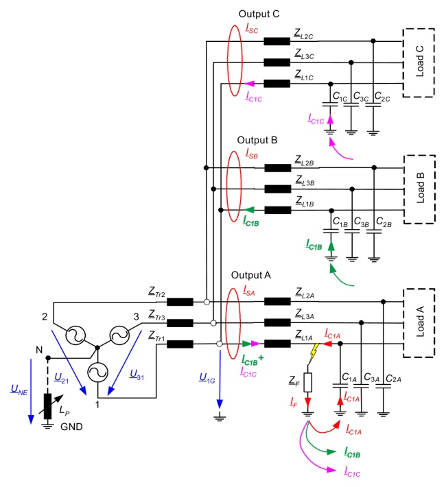
Discharge of the faulty conductor across earth
The lines can be considered as a distributed network with a complex series impedance ZLXX and a phase-earth capacitance CXX . Most highest probability for the first ignition of the arc is near the maximum of the phase-earth voltage U1E. At this time the load on the conductor is also the largest. The discharge of the conductor 1 begins at the point of failure and spreads like a wave in both directions to the ends of conductor 1. The propagation of the wave to the two healthy conductors is consequently blocked. The effect is also suppressed by a Petersen coil. More often there is a reflection of the wave at the ends of the conductor or at any point with a change of the characteristic impedance, such as in a substation or at a distribution point with a transition from one line to two or more. This reflection can be seen as a high-frequency oscillation in both the zero-voltage and zero-current.
Important parameters for the behaviour of the discharge are:
- Phase-earth capacitance of conductor 1
- Charge state of the phase-earth capacitance before the first ignition of the arc
- ZL series impedance of conductor 1 in the faulty output and in healthy outputs
- Impedance ZF at the fault point, which also includes the earth impedance.
The discharge frequency substantially depends on the series impedance and the phase-earth capacitance, which in a first approximation is proportional to the conductor length. The discharge frequency is higher for small networks and lower for large networks. Usually, the discharge frequency is in the range above 10 kHz.