Changes in Energy Technology – Part 2

Veränderungen mit Blick auf Power Quality

Standards play a major role for power quality measurements. Accordingly, it is essential that these standards are also adapted to the new conditions in the course of the change in energy technology. In the second article of our series, we look at the current standards and how they should be interpreted with regard to high switching frequencies.

The choice of the standard is essential for the success of the measurement evaluation.

For each measurement in the field of power quality, it is important to consider the standards that apply to the respective network. Two standards are frequently chosen in the course of voltage harmonics in the low-voltage grid: EN 50160 and IEC 61000-2-2. Today’s EN 50160 is limited because it does not define compatibility levels for the public grid above the 25th harmonic.

Accordingly, the IEC 61000-2-2, which describes the characteristics for compatibility levels for low-frequency conducted disturbances and signal transmissions in public low-voltage networks, can be added to the EN 50160 for a measurement. Comparing the two standards with each other, the following difference in regard to measurement will be noticed:

  • The EN 50160 is intended for the transfer point to the customer: In the low voltage grid, the measurement would be conducted at the customer’s house connection.
  • The IEC 61000-2-2 describes the so-called PCC (= Point of coming Coupling), which means that the point is considered where other consumers come in.

According to the IEC standard, if a cable distribution box is used and a 100 m long line to customer A and another line to customer B is connected to this cable distribution box, the appropriate measuring point in this case would be the cable distribution box. In this case, this would be the PCC. If measurements were taken in a multi-family house with several meters, the measuring point would be the meter and thus the same for both the EN 50160 and the IEC 61000-2-2.

The IEC 61000-2-2

Until lately, there was a gap in the IEC 61000-2-2 between the 50th harmonic and 150 kHz. This means that up to the 50th harmonic there were compatibility values in the network. From 150 kHz upwards, there have always been EMC standards up to a few GHz. These defined what interference a consumer was allowed to emit. The range above the 50th harmonic up to 150 kHz was not regulated until 2018. This means that if a consumer emits, for example, 8 kHz into the network and disturbs other consumers with it, no limit value was violated until then.

Figure 1 provides an overview of the valid levels up to 9 kHz.

Figure 1: Compatibility level for low-frequency conducted disturbances in the public low-voltage grid

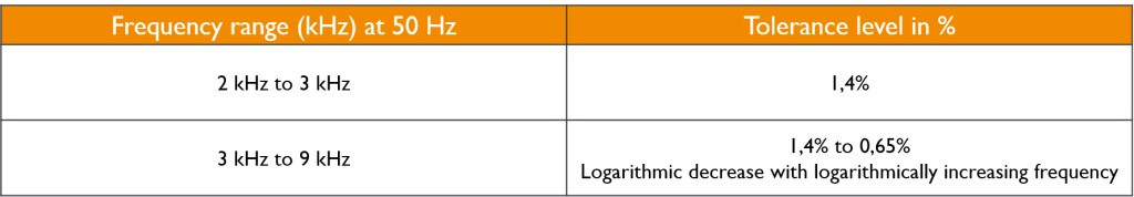
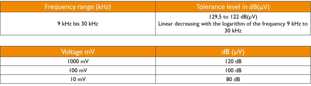
Figure 2 shows the limit value in the range from 9 kHz to 30 kHz. What is somewhat striking for power engineers at this point: Normally, people are used to defining the compatibility levels in absolute values or in % deviation from the nominal value, but this standard defines it in dB(μV). A little help how to convert these values into mV values is given in the lower part of the figure.

Figure 2: Compatibility level for low-frequency conducted disturbances in the public low-voltage grid

Limit values of the VDE connection guidelines

Taking a look at the VDE connection guidelines (VDE AR-N-4100/ VDE AR-N-4110/ VDE AR-N-4120/ VDE AR-N-4130), for example, it becomes apparent that limit values for currents up to 9 kHz are also defined here. At this point, the power quality moves from the low-frequency to the range of higher switching frequencies.

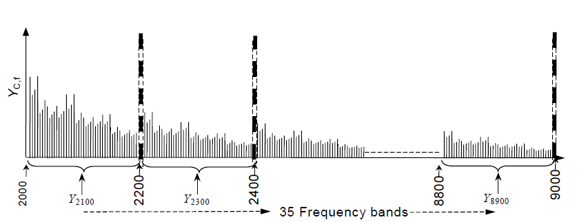
For the connection of a customer installation to the low-voltage grid, there would be compatibility values for the currents of a customer installation of 2 kHz to 9 kHz according to Figure 3. The special feature of this case is that it is not a multiple of 50 Hz. In the range between 2 kHz and 9 kHz, 200 Hz bands are always combined.

The upper part of picture 3 shows that in the range between 8.8 kHz and 9 kHz all spectral lines are grouped by the measuring device and the centre frequency is indicated. An 8.9 kHz accordingly means that all repercussions between 8.8 kHz and 9 kHz are included and for this range limit values are defined.

Figure 3: Measurement 2 to 9 kHz in 200 Hz bands according to IEC 61000-4-7

Examples of standard evaluations

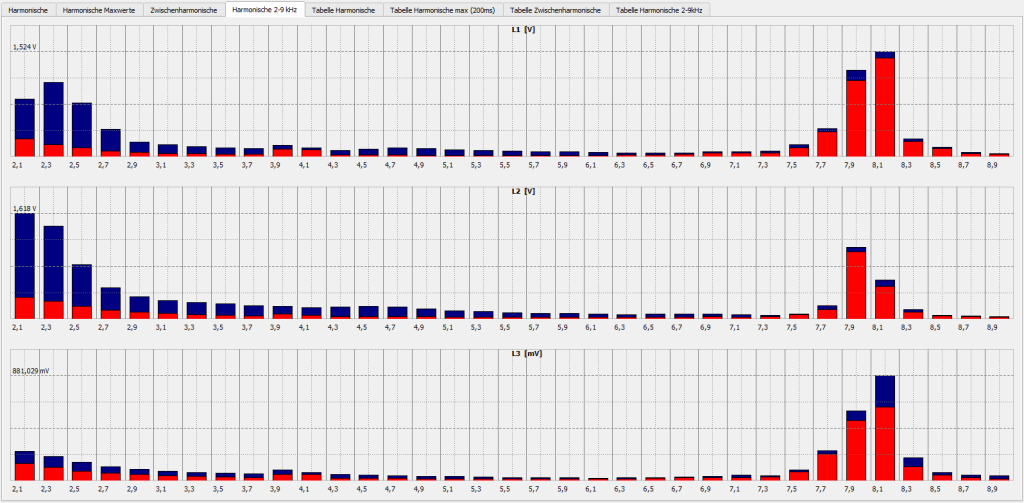
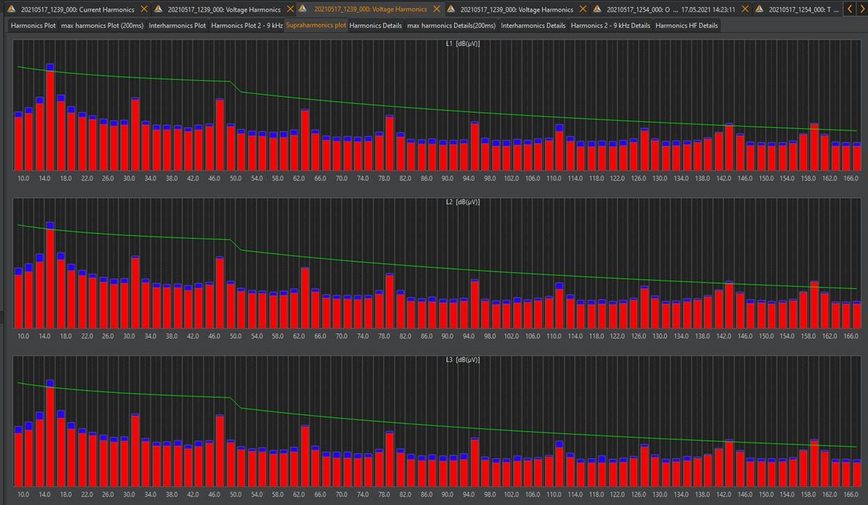
A standard evaluation could proceed as follows: Over the period of one week, the power quality is measured in the range up to 150 kHz (see Figure 4). The limit value line can be displayed via the WinPQ mobile software. Our software offers the option of displaying this as a percentage in relation to the fundamental or in dB(μV). You can see in the measurement that the higher the frequencies, the lower the limit value. In this example, limit violations can be detected.

Figure 4: Limit Values 2 to 150 kHz (in dB/µV)

Another practical example was carried out at a University of Applied Sciences. The University has a large solar system as well as several charging stations for e-mobiles. Now it was investigated what influence the e-mobiles have on repercussions in the grid. Customers and various energy suppliers suspected that different vehicles are not compatible with each other in the grid and stop charging due to mutual interference if another vehicle is charged in parallel.

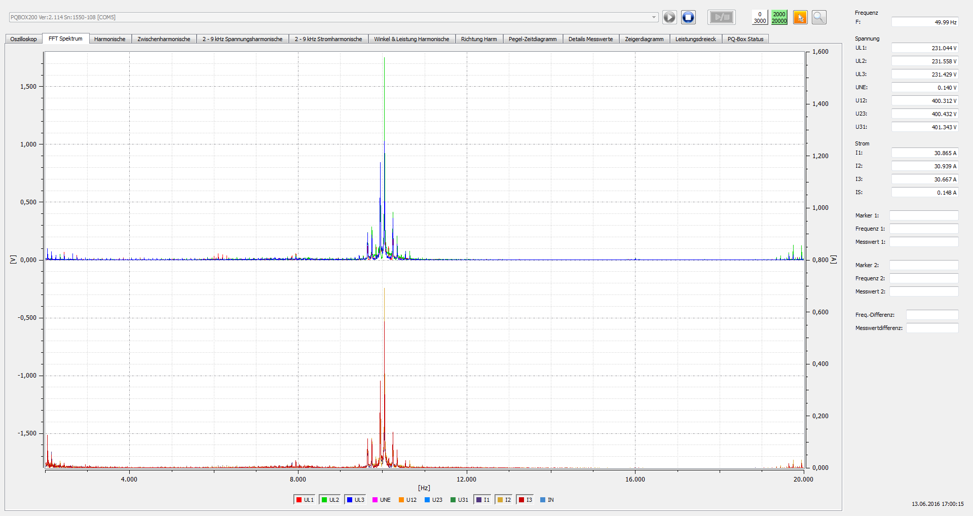
Figure 5 shows the measurement of an e-mobile at the charging station. The graph shows a mains feedback at 10 kHz on the current. This is the switching frequency of the charge controller in the vehicle. The upper graph shows the feedback on the voltage via the impedance of the grid. In our case, the voltage level is 1.75 V. As already described: The 10 kHz with 1.75 V look for some consumer through which they can short-circuit. In fact, vehicles can interfere with each other in such a way that the charging process is interrupted. The entire measurement can be found in our application report Parallel Charging of Electric Vehicles.

Figure 5: Measurement of an E-Mobile: voltage and current – 10 kHz level

Author
Jürgen Blum, Product Manager Power Quality Mobile

Want more information about our products?

Contact us here!


Contact

News from the product group

PQMobil - News

General Knowledge

Voltage Monitoring

Find out everything you need to know about voltage monitoring in this article. What is voltage monitoring, why is voltage monitoring essential for both energy supply companies and industrial companies and how is it implemented in compliance with standards?

Read more

General Knowledge

What Is Load Profile Measurement/Power Measurement?

This article explains the definition and difference between load profile measurement (RLM), power measurement and measuring the standard load profile. These are important methods for accurately recording energy consumption in commercial, large industrial plant as well as in the public energy grid.

Read more

Training Video

»PQMobil« Training Video 4: Create and Configure PQ Reports With Software WinPQ mobil

This video explains everything about creating and configuring power quality reports with »WinPQ mobil«.

Read more

Training Video

»PQMobil« Training Video 3: Usability & Functions of the PQ-Box App

This video gives you an introduction to the usability and functions of the »PQ-Box App« for our portable power quality analysers.

Read more

Training Video

»PQMobil« Training Video 2: Menu Navigation and Operation of the PQ-Box

In this short introductory video, we present to you how to navigate and operate our portable power quality analysers »PQ-Box 150«, »PQ-Box 200« & »PQ-Box 300« of the PQ-Box family.

Read more

Training Video

»PQMobil« Training Video 1: Getting Started with the PQ-Box

This video shows in detail how to connect the »PQ-Box« and record measurements. The »WinPQ mobil« software is then used to visualize and analyse the measurement data and create a report.

Read more

General Knowledge

Residual current

In this article, you will learn about residual current measurement & residual current monitoring and why it is important to measure residual current.

Read more

General Knowledge

Power Quality

Good power quality is characterized by the fact that the mains voltage actually arriving at the consumer matches the mains voltage promised by the utility company.

Read more

General Knowledge

Reactive power – definition, calculation and measurement

The key role of reactive power in electrical engineering: definition, calculation, measurement and the differences to active power and apparent power. Find out how reactive power influences the efficiency of electricity grids and shapes energy transmission.

Read more

General Knowledge

What is apparent power and how is it calculated?

This article addresses the question of what apparent power is and how to calculate it. An understanding of apparent power is crucial for the correct dimensioning of inverters and therefore for the optimum efficiency and performance of photovoltaic systems.

Read more

Info letter

Information Letter No. 24: Integration guide for the metering of a power plant according to the Requirements for Generators (2016/631) RfG

Integration guide for the measurement of a power plant (EZA) according to VDE-AR 4110 and VDE-AR 4120.

Read more

Info letter

Info Letter No. 23: Direction of harmonics Sources of harmonics in the power system

Le sens du flux de puissance des harmoniques est déterminé par le signe de la puissance activ

Read more

Info letter

Info Letter No. 22: Definition of power measurements according to the standards DIN 40110-2 and IEEE 1459

There is a wide range of electronic measuring devices for the digital measurement of power...

Read more

Info letter

Info Letter No. 20: Capacitance of conductors

In the conductors of electrical power supplies, a distinction is made between the operating capacitance...

Read more

Info letter

Info Letter No. 19: The evaluation of power quality and detection of interference in medium voltage network

For various reasons, interest in the continuous monitoring of network quality in medium-voltage...

Read more

Info letter

Info Letter No. 8: Apparent power and reactive power in three-phase networks

The range of electromechanical and electronic measuring devices in analog - and digital technology...

Read more

Info letter

Info Letter No. 5: Zero sequence voltage in three-phase networks

With balanced network operation and inequality of the impedances in the consumer circuit, the phase...

Read more

Info letter

Info Letter No. 4: Summation of Alternating Currents

For the parallel connection of power sources, the principle of superposition applies, when all resources...

Read more

Info letter

Info Letter No. 2: Measurement Transformers in three-phase networks (Part 2)

In a symmetrically loaded three-wire three-phase network, a two-pole insulated voltage transformer...

Read more

Info letter

Info Letter No. 1: Measurement Transformers in three-phase networks (Part 1)

The direct connection of measuring devices into the network is limited for safety reasons to values...

Read more

Special Publication

Ferrari´s Meter vs. Electronic Meter

This technical report analyzes a power measurement at a large industrial customer. The customer records very high currents and fifth harmonic voltages during production time, which leads to poor voltage quality.

Read more

Special Publication

Angle determination of voltage and current harmonics in practice

Today's devices and equipment such as switched-mode power supplies, frequency converters, regulated drives, charging devices for e-mobiles or LED lighting work internally with high clock frequencies in order to regulate power efficiently. These can lead to both conducted and field-bound (coupled) influences in the energy grid. In this technical report, we explain how you can detect these sources of interference in the grid using suitable measuring technology.

Read more

General Knowledge

All „Supra“ with your grid?

Today's devices and equipment such as switched-mode power supplies, frequency converters, controlled drives, charging devices for e-mobiles or LED lighting work internally with high clock frequencies in order to regulate power efficiently. These can lead to line-borne as well as field-borne (coupled) interference in the power grid. In this technical report, we explain how you can detect these sources of interference in the grid using suitable measurement technology.

Read more

General Knowledge

Power Quality Analysis: Tips and Tricks II

Useful tips & tricks for handling Power Quality measuring devices and typical user errors - now in our two-part article! This article provides further insights and practical tips and application examples for power quality analysis.

Read more

General Knowledge

Power Quality Analysis: Tips and Tricks I

Useful tips & tricks for handling Power Quality measuring devices and typical user errors - now in our two-part article! This article explains tips and tricks for performing power quality measurements. It explains which connection errors can be made and which preliminary considerations should be made before using a measuring device.

Read more

Contact request:


* Mandatory

Your data is being processed

a-eberle kontakt newsletter ×

Our seminars &
webinars

► Register here!

x